English
Tube deformation during punching is a common production problem when processing square tubes, rectangular tubes, round pipes, aluminum profiles, and other hollow metal sections.
The finished workpiece may show flattening, dents, cracks, irregular holes, excessive burrs, wall collapse, or inaccurate hole positions. These problems can increase scrap, require secondary correction, affect welding and assembly, and reduce batch-production consistency.
However, deformation is not always caused by insufficient machine pressure. In many cases, the real cause is unsuitable tooling, incorrect die clearance, inadequate tube support, poor clamping, worn punches, material variation, or an unreasonable hole layout.
This article explains eight common causes of tube deformation during punching and the practical steps manufacturers can take to improve the finished result.
What Does Tube Deformation During Punching Look Like?
Tube deformation can appear in several different forms:
- The tube wall collapses around the hole
- A square or rectangular tube becomes flattened
- The hole becomes oval instead of round
- The hole dimensions are larger or smaller than required
- The material cracks near the punched area
- The tube surface develops dents or pressure marks
- The hole edge has excessive burrs
- The opposite wall is damaged
- The tube twists after several holes are punched
- Hole positions become inconsistent during batch production
Different defects usually indicate different causes.
For example, local wall collapse is often related to insufficient support, while excessive burrs may be related to worn tooling or unsuitable punch-to-die clearance. A hole that changes position from one workpiece to another may be caused by feeding, clamping, or material movement rather than the punching die itself.
Why Is Tube Punching More Difficult Than Flat-Sheet Punching?
A flat metal sheet is normally supported by the machine table and lower die around the punching area.
A hollow tube has an unsupported internal space. When the punch applies force to one wall, the tube may bend, flatten, twist, or transfer the load to the opposite wall.
The difficulty increases when processing:
- Thin-wall tubes
- Large holes
- Holes close to the tube edge
- High-strength materials
- Stainless steel
- Small tubes with limited internal space
- Several closely spaced holes
- Holes on multiple sides
- Open or asymmetrical profiles
- Tubes with inconsistent wall thickness
For this reason, tube-punching tooling must be designed around the actual material and profile rather than treated as ordinary flat-sheet tooling.
1. Insufficient Internal or External Tube Support
One of the most common causes of tube deformation is inadequate support around the punching area.
When the punch enters the tube wall, the material is subjected to concentrated force. If the tube is not supported correctly, the wall may move inward before the material is fully sheared.
This can cause:
- Local dents
- Wall collapse
- Tube flattening
- Oval holes
- Cracking around the hole
- Damage to the opposite wall
- Inconsistent hole dimensions
How to Solve It
Depending on the tube shape and hole position, the tooling may require:
- An internal mandrel
- An internal support block
- A removable support plug
- A shaped lower die
- External clamping blocks
- Side-support plates
- Guide sleeves
- Profile-specific locating fixtures
The support should match the internal or external shape of the profile as closely as practical.
For square and rectangular tubes, a shaped support block can help resist wall movement. For round pipes, curved support surfaces are normally required to prevent rolling and flattening.
The support design should also allow punched scrap to leave the cutting area without becoming trapped inside the tube or tooling.
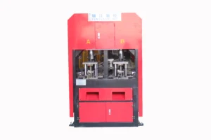
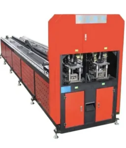
A support structure suitable for one tube size may not work correctly for another size. When several profiles are processed on the same machine, interchangeable supports or adjustable fixtures may be required. For repeated tube processing, an automatic punching machine can be configured with customized dies, support fixtures, clamping, and servo feeding.
2. Incorrect Punch-to-Die Clearance
Punch-to-die clearance is the gap between the cutting edge of the punch and the cutting edge of the die.
The correct clearance depends on factors such as:
- Material type
- Material strength
- Wall thickness
- Hole shape
- Tool dimensions
- Punching direction
- Required burr level
If the clearance is too tight, the machine may require more punching force. Tool wear can increase, the material may be pulled or compressed excessively, and the tube wall may deform.
If the clearance is too large, the hole may show greater rollover, poor dimensional control, rough fracture surfaces, or excessive burrs.
Tooling manufacturers emphasize that appropriate die clearance helps control punching force and produces a cleaner hole with less burr; excessively tight clearance can increase tonnage, tool wear, debris and part deformation. (Mate Precision Technologies)
How to Solve It
Do not use one fixed clearance for every material.
Before manufacturing the tooling, confirm:
- Exact material grade
- Actual wall thickness
- Maximum thickness variation
- Required hole dimensions
- Required hole tolerance
- Acceptable burr direction
- Whether the hole is pierced or blanked
- Whether several walls are punched in one cycle
The punch and die should also be checked after sharpening. Tool maintenance may change their effective dimensions, and the clearance should remain suitable throughout the usable tool life.
When processing several materials on one machine, separate punches and dies may be required.
3. The Hole Is Too Large for the Tube or Wall Thickness
A large hole removes more material and applies force across a wider section of the tube wall.
When the hole diameter or slot width is large compared with the tube dimensions, the remaining material may not have enough rigidity to maintain the original profile shape.
This problem is more noticeable when:
- The tube wall is thin
- The hole is close to a corner
- The hole removes most of one side
- Several large holes are positioned close together
- The tube has no internal support
- The material has limited ductility
- A rectangular or irregular hole has sharp corners
A large rectangular opening may cause more visible deformation than a smaller round hole because the cutting perimeter and remaining wall structure are different.
How to Solve It
Possible solutions include:
- Increasing support around the punching area
- Redesigning the punch and die
- Dividing one large feature into several processing steps
- Adding corner radii to rectangular openings
- Moving the hole farther from the profile edge
- Changing the punching direction
- Using several stations
- Reducing the number of holes punched simultaneously
- Using laser cutting for complex or oversized openings
The final method should be confirmed through a sample test using the customer’s actual material.
A design that works on thick carbon steel may still deform when applied to a thin aluminum or stainless steel tube.
4. The Punching Force or Speed Is Not Properly Controlled
Selecting a larger hydraulic cylinder does not automatically solve deformation.
The machine needs enough force to complete the punching process, but force must be applied through suitable tooling, support, alignment, and stroke control.
Problems may occur when:
- The machine does not have enough force
- The pressure is set unnecessarily high
- The punch enters the material too quickly
- The return stroke is too fast
- The punch travels deeper than necessary
- Several holes are punched simultaneously without sufficient support
- Hydraulic pressure fluctuates
- The material moves during the stroke
Insufficient force may result in incomplete shearing, tearing, trapped scrap, or the punch stopping inside the material.
Excessive or poorly controlled force can increase impact, tool stress, vibration, marking, and material movement.
How to Solve It
The machine configuration should be determined from:
- Hole perimeter
- Material thickness
- Material shear strength
- Number of holes punched at the same time
- Punch geometry
- Required production speed
- Tooling structure
The hydraulic system should allow stable pressure and controlled movement. Review our hydraulic punching machine selection guide for more information about punching force, tooling, feeding, and machine configuration.
Useful adjustments may include:
- Punching pressure
- Approach speed
- Working speed
- Stroke length
- Return speed
- Dwell time
- Material-clamping sequence
- Feeding and punching timing
The punch should normally travel only far enough to complete the cut and release the material correctly. An unnecessarily long stroke increases cycle time and may increase tool or material stress.
5. Worn, Damaged, or Misaligned Punching Tools
A sharp, correctly aligned punch concentrates cutting force at the intended cutting edge.
As the tool becomes dull, it may require more force to penetrate the material. The material may be compressed or dragged before the cut is completed, increasing burrs and deformation.
Common tooling problems include:
- Dull punch edges
- Chipped punch corners
- Worn die openings
- Uneven sharpening
- Punch bending
- Punch and die misalignment
- Loose tool holders
- Damaged guide components
- Incorrectly installed dies
- Material buildup on the punch
Proper alignment, suitable clearance, sharp tools and correct lubrication are important for consistent punching quality and tool life. Partial hits, notching and shearing can also create lateral forces that deflect a punch and tighten clearance on one side. (Mate Precision Technologies)
How to Solve It
Create a regular tooling-inspection schedule.
Check:
- Punch cutting edges
- Die cutting edges
- Tool alignment
- Guide condition
- Fasteners
- Punch straightness
- Die opening dimensions
- Material buildup
- Lubrication
- Tool height after sharpening
Do not wait until the finished parts show severe burrs before maintaining the tooling.
A small change in burr height, punching sound, required pressure, or hole appearance may indicate that the tool needs inspection.
Replacement punches and dies should be prepared for high-volume production so that worn tools do not stop the entire line.
6. Poor Clamping, Feeding, or Workpiece Positioning
Even when the punching tooling is correct, the tube can deform or produce inaccurate holes if it moves during the punching cycle.
Movement may be caused by:
- Insufficient clamping force
- Clamps that do not match the profile
- Oil or debris on the material
- Worn guide rollers
- Incorrect feeding height
- Long unsupported tubes
- Material vibration
- Misaligned feeding racks
- Excessive acceleration
- Tube twisting during movement
A round pipe can rotate if it is not clamped properly. A long square tube can sag between supports. A thin profile can slide or bend when the clamp applies uneven force.
How to Solve It
The feeding and clamping system should be configured according to:
- Profile shape
- Tube dimensions
- Material length
- Workpiece weight
- Wall thickness
- Surface condition
- Hole direction
- Required positioning accuracy
Possible improvements include:
- Profile-specific clamp jaws
- Additional support rollers
- Adjustable guide rails
- Reduced feeding acceleration
- Improved servo parameters
- More stable loading racks
- Anti-rotation fixtures
- Clamping before the punch begins moving
- Sensor confirmation of material position
During testing, check both the first and last workpieces in a batch.
A machine may produce an accurate first part but gradually lose position because of material slipping, accumulated feeding error, loose clamps, or inconsistent raw material.
7. Material Properties or Wall Thickness Are Inconsistent
Two tubes with the same outside dimensions may behave differently during punching.
The result can change because of differences in:
- Material grade
- Tensile and shear strength
- Hardness
- Ductility
- Heat treatment
- Surface coating
- Weld seam
- Wall-thickness tolerance
- Residual stress
- Manufacturing method
For example, stainless steel, carbon steel, galvanized steel, and aluminum do not require identical tooling conditions.
A die designed and tested with one material may produce cracks, excessive burrs, or deformation when used with another material.
Welded tubes also contain a longitudinal seam. The seam area may have different hardness and thickness from the rest of the tube wall.
How to Solve It
Before confirming the machine and tooling, provide:
- Material standard
- Material grade
- Actual wall thickness
- Thickness tolerance
- Sample material
- Seam position
- Surface-treatment information
- Photos of existing defects
Do not rely only on a general description such as “steel tube” or “stainless tube.”
When the seam position affects the punching result, the loading and locating system may need to keep the seam away from the punching area.
A sample test should use material that is representative of normal production, not only the easiest sample available.
8. Holes Are Too Close to Edges, Corners, Seams, or Other Holes
The hole layout has a major influence on tube stability.
When a hole is too close to an edge or corner, there may not be enough surrounding material to resist punching force.
When several holes are too close together, the remaining strip of material may stretch, twist, crack, or buckle.
Problems can also occur when:
- A hole crosses the tube weld seam
- A hole is positioned near the tube end
- Several holes are punched in a straight line
- Holes are required on opposite walls
- Multiple sides are punched in one station
- A notch removes part of a tube corner
- The punching sequence concentrates stress in one area
Repeated punching can progressively increase distortion, especially when many features are placed close together or processed in an unsuitable sequence. Tooling guidance for distortion control recommends considering clearance, tooling arrangement and hit sequence rather than treating each hole as an isolated operation. (Wilson Tool International)
How to Solve It
Review the complete product drawing before designing the machine.
Possible improvements include:
- Increasing the distance between holes
- Moving holes away from corners
- Moving holes away from the weld seam
- Changing the punching sequence
- Alternating punching positions
- Dividing the process between several stations
- Punching one side before another
- Adding support between nearby holes
- Changing the hole shape
- Using laser cutting for highly concentrated features
When the drawing cannot be changed, the tooling and process sequence must be developed specifically for that layout.
Other Problems That Can Be Mistaken for Tube Deformation
Not every defective part is caused by the tube collapsing.
Similar-looking problems may come from:
Excessive Burrs
Possible causes include:
- Worn tools
- Incorrect clearance
- Misalignment
- Material variation
- Damaged die edges
Hole-Position Errors
Possible causes include:
- Material slipping
- Servo-feeding errors
- Incorrect program settings
- Sensor problems
- Loose clamps
- Unstable material support
Cracks Around the Hole
Possible causes include:
- Low material ductility
- Hole too close to an edge
- Sharp tool corners
- Inadequate support
- Excessive local deformation
- Incorrect clearance
Scratches and Pressure Marks
Possible causes include:
- Dirty fixtures
- Metal chips
- Excessive clamping force
- Rough support surfaces
- Damaged guide rollers
- Material dragging during feeding
Correctly identifying the defect helps avoid unnecessary changes to hydraulic pressure or machine size.
How to Reduce Tube Deformation in Batch Production
For stable batch production, consider the complete system rather than one component.
A reliable process normally requires:
- Material matched to the approved sample
- Correct punch-to-die clearance
- Sharp and aligned tooling
- Profile-specific internal or external support
- Stable clamping
- Controlled feeding
- Appropriate hydraulic pressure
- Suitable punching speed
- A reasonable hole layout
- Regular tooling maintenance
- Programmed production parameters
- Sample testing before mass production
The first-off workpiece should be inspected before continuous production begins.
Inspection can include:
- Tube dimensions before and after punching
- Hole dimensions
- Hole position
- Burr direction and height
- Tube flatness
- Surface marks
- Cracks
- Opposite-wall damage
- Finished-part length
For long production runs, inspections should also be performed at defined intervals because tool wear and material variation may gradually affect the results.
When Should Laser Cutting Be Considered Instead?
Punching is generally effective when:
- Hole shapes are repeated
- Production quantities are medium or high
- Product designs are stable
- Dedicated tooling is economical
- Short cycle time is important
- Automatic feeding is required
Laser tube cutting may be more suitable when:
- Hole and notch shapes change frequently
- Complex contours are required
- Many different products are processed
- Holes are concentrated in one area
- Dedicated tooling is uneconomical
- Digital program changes are important
- Several cutting features are required on one tube
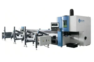
Laser cutting does not automatically eliminate every deformation problem. Thin tubes may still require suitable chuck pressure, material support, cutting parameters, and heat control. An automatic laser tube cutting machine can process changing holes, slots, notches, and contours without manufacturing a dedicated die for every design.
The correct decision should be based on the product drawing, production quantity, material, tolerance, cycle time, tooling cost, and future product variety. For a broader process comparison, read our guide to tube punching machines vs laser cutting machines.
Information to Provide When Requesting a Tube Punching Solution
To help the machine manufacturer evaluate deformation risks, provide:
- Material type and grade
- Tube or profile drawing
- Outside dimensions
- Wall thickness
- Wall-thickness tolerance
- Maximum material length
- Workpiece weight
- Hole shape and dimensions
- Hole position
- Distance between holes
- Distance from holes to edges
- Number of processing sides
- Weld-seam position
- Finished-part length
- Required tolerance
- Daily or monthly production quantity
- Photos of current deformation problems
- Actual material samples
Complete information allows the engineering team to evaluate the tooling, support structure, punching force, feeding system, clamping method, number of stations, and production sequence.
Safety Considerations
Tube-punching equipment contains a hazardous point of operation between the punch and die.
Operators should not place their hands near the tooling during the machine cycle. Depending on the machine design and local requirements, suitable safeguards may include fixed guards, interlocked guards, two-hand controls, safety light curtains, guarded foot controls, emergency stops, and protected hydraulic or transmission components.
OSHA guidance states that hydraulic presses should use appropriate guarding to protect personnel from point-of-operation and nip-point hazards, and guarded foot controls and accessible emergency stops may also be required.
Tool changes, maintenance, cleaning, and jam removal should only be carried out according to the machine’s safety procedures and applicable lockout requirements.
Conclusion
Tube deformation during punching is usually caused by a combination of material, tooling, support, machine settings, and product design.
Increasing hydraulic pressure alone will not correct unsuitable clearance, worn tooling, poor support, material movement, or an unreasonable hole layout.
The most effective solution is to review the complete process:
- Material
- Profile dimensions
- Wall thickness
- Hole design
- Tooling clearance
- Tube support
- Clamping
- Feeding
- Hydraulic settings
- Punching sequence
Before ordering a machine or new tooling, send the actual tube drawing, hole layout, material information, production quantity, and representative samples to the engineering team.
A proper sample test can help confirm hole quality, tube deformation, tool structure, feeding accuracy, cycle time, and batch-production stability.
Frequently Asked Questions
Why does a square tube flatten during punching?
A square tube may flatten when the punching wall does not have enough internal or external support.
Incorrect tooling clearance, excessive force, thin walls, large holes, or poor clamping may also contribute to the problem.
Can an internal mandrel prevent tube deformation?
An internal mandrel or support block can help resist wall collapse in many applications.
However, its shape, position, clearance, strength, and scrap-removal design must match the actual tube and hole layout.
Does higher hydraulic pressure reduce deformation?
Not necessarily.
The machine must provide enough force to complete the cut, but excessive pressure cannot correct unsuitable tooling, incorrect clearance, poor support, worn punches, or material movement.
Why are punched holes becoming oval?
Oval holes may be caused by tube deformation, material movement, punch misalignment, worn tooling, incorrect clearance, or insufficient support around the punching area.
Why do burrs increase after producing many parts?
Increasing burrs can indicate punch or die wear, material buildup, alignment problems, changed clearance, or inconsistent raw material.
The tooling should be inspected and maintained before the defect becomes severe.
Can thin-wall tubes be punched without deformation?
Many thin-wall tubes can be punched successfully with suitable tooling, internal or external support, controlled clamping, correct clearance, and appropriate machine settings.
A sample test is recommended before confirming production tooling.
Should holes be punched near the tube weld seam?
Punching near or across a weld seam may produce inconsistent results because the seam can have different hardness, thickness, or structure.
The seam position should be identified during loading and considered when designing the hole layout and fixtures.
When should laser tube cutting replace punching?
Laser cutting may be more suitable when the design contains complex contours, frequently changing patterns, concentrated features, low production quantities, or shapes that would require several expensive punching dies.